Hybrid Cable and Network Cable Making
Making a Fusion-Splicing hybrid cable(Recommend)
Making a Cold-Connection hybrid cable(Restricted use)
Making a 2-Core RJ45 Power Connector of a hybrid cable
Making a CAT6A Industrial Registered Jack (RJ)
Making a CAT6A Female Connector
Making a CAT5e Network Cable
Note: It's recommend to make a hybrid cable by fusion-splicing.
Making a Fusion-Splicing hybrid cable(Recommend)
For a hybrid cable delivered with optical fiber connectors, you can quickly perform optical fiber fusion splicing for the fiber and the connector. Optical fiber fusion splicing requires a fiber fusion splicer. The procedure is described as follows:
Preparations
-
Prepare materials. Required materials:
-
Optical-fiber heat-shrinkable sleeve: 60 mm long and reinforced with stainless steel wires.
-
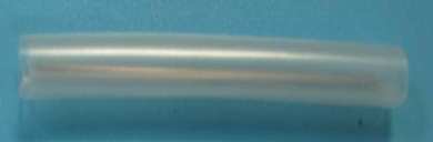
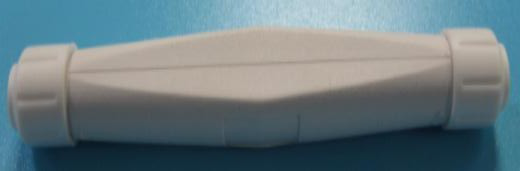
Fusion-splicing protective tube
-
Optical-fiber pigtail cable: a G.657A2 single-mode optical-fiber pigtail cable with a finished LC connector. The recommended length of the pigtail cable is 50 cm.
-
Butterfly-shaped sub-cable of the hybrid cable: a 50 cm sub-cable peeled off from the hybrid cable.
-
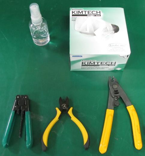
Prepare tools. Required tools:
-
Sheath cable stripper: used to peel off the butterfly-shaped cable in a hybrid cable to remove the steel wires and outer sheaths.
-
Diagonal pliers: used to cut optical cables.
-
Miller pliers: used to peel off the inner and outer sheaths of pigtail cables and the coating of optical fibers.
-
Dust-free paper (with alcohol): used to clean the fiber core whose coating is stripped off.
-
Prepare devices. Required devices:
-
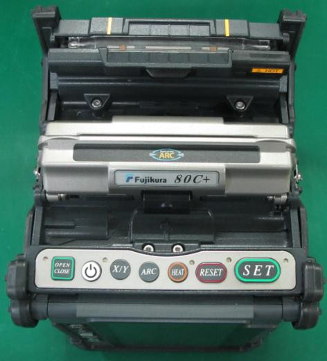
Single-core fiber fusion splicer: It is recommended to use a Fujikura 80C+ or another mainstream product with the fiber-core alignment function.
-
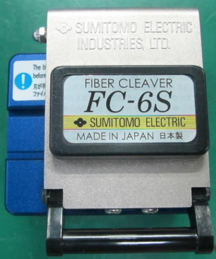
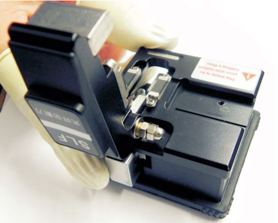
Optical fiber cutting knife: It is recommended to use a SUMITOMO FC-6S or another mainstream product with the same functions.
Installing an Optical Fiber Connector
-
Set the fiber fusion splicer.
-
Clean the fusion splicer: Clean the optical fiber clamp, fixing area, and discharge electrode in accordance with the user manual for the device.
If the number of times that the electrode is discharged is close to the upper limit, replace the electrode with a new one with the same brand in a timely manner.
-
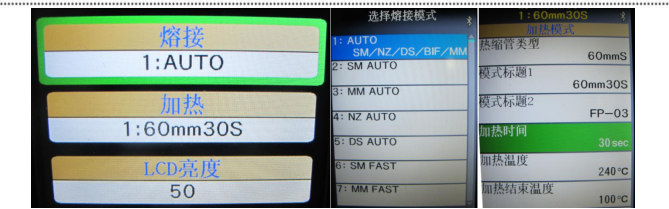
Set the splicing mode to AUTO mode for the optical fiber.
-
Set the heating mode of the heat-shrinkable sleeve as follows:
Length of the heat-shrinkable sleeve: 60 mm
heating time: 30 s
heating temperature: 240℃
temperature at the end of heating: 100℃.
Or, use the heat-shrinkable sleeve to perform an actual test on the fusion splicer, and then determine the heating mode.
Note: The heating time depends on the degree to which the heat-shrinkable sleeve is completely melted into a whole and is transparent.
-
Make preparations before optical fiber fusion splicing.
-
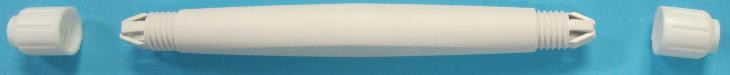
Remove the nuts at the two ends of the fusion-splicing protective tube to show the claws at the ends.
Make the optical-fiber pigtail cable pass through the fusion-splicing protective tube and a nut in turn.
-
Make the butterfly-shaped sub-cable of the hybrid cable pass through the heat-shrinkable sleeve and the other nut in turn.
-
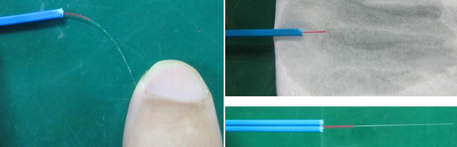
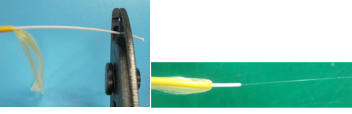
Make the optical fiber in the butterfly-shaped cable.
-
Use the sheath cable stripper to peel off the butterfly-shaped cable to expose the optical fiber for over 40 mm.
-
Use the Miller pliers to strip off the coating on the optical fiber.
Note: A coating of about 5 mm should be reserved at the tail end of the optical fiber.
-
Bend the optical fiber in the horizontal direction and vertical direction three times respectively, at a bending angle of about 60°. If the fiber is not broken, it indicates that the fiber is not damaged.
-
Use the dust-free paper soaked with alcohol to wipe the optical fiber in the horizontal direction and vertical direction respectively to remove the coating and dust from the optical fiber.
Note: Do not make the wiped fiber touch other objects.
-
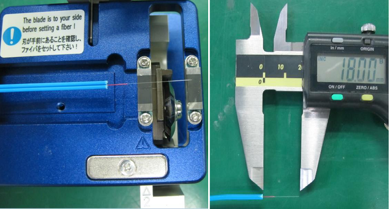
Use the optical fiber cutting knife to cut the optical fiber. Ensure that the total length of the optical fiber is 16~20 mm after being cut. It is recommended that the length of the remained optical fiber be 18 mm.
Note: When cutting the optical fiber, make sure that the optical fiber is 90° perpendicular to the knife.
The optical fiber, after being cut, especially the end face, is prohibited to touch other objects. Otherwise, the optical fiber should be cut again.
-
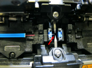
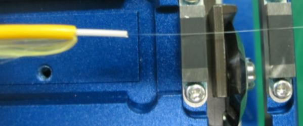
Place the optical fiber on the fusion splicer side carefully and fix it. Ensure that the front end of the optical fiber is placed between the base and the electrode. Otherwise, the optical fiber cannot be fusion-spliced.
-
Make the optical-fiber pigtail cable.
-
Use the Miller pliers to peel off the outer sheath of the tail cable for more than 40 mm, and keep the aramid fiber.
-
Use the Miller pliers to peel off the protective layer of the optical fiber segment by segment.
Keep a protective layer of about 5 mm at the end of the optical fiber.
-
Bend the optical fiber in the horizontal direction and vertical direction three times respectively, at a bending angle of about 60°. If the fiber is not broken, it indicates that the fiber is not damaged.
-
Use the dust-free paper soaked with alcohol to wipe the optical fiber in the horizontal direction and vertical direction respectively to remove the coating and dust from the optical fiber.
Do not make the wiped fiber touch other objects.
-
Use the optical fiber cutting knife to cut the optical fiber. Ensure that the total length of the optical fiber is 16–20 mm after being cut. It is recommended that the length of the remained optical fiber be 18 mm. The optical fiber, after being cut, especially the end face, is prohibited to touch other objects.
Note: When cutting the optical fiber, make sure that the optical fiber is 90° perpendicular to the knife.
-
Place the optical fiber on the other side of the fusion splicer carefully and fix it. Ensure that the front end of the optical fiber is placed between the base and the electrode. Otherwise, the optical fiber cannot be fusion-spliced.
-
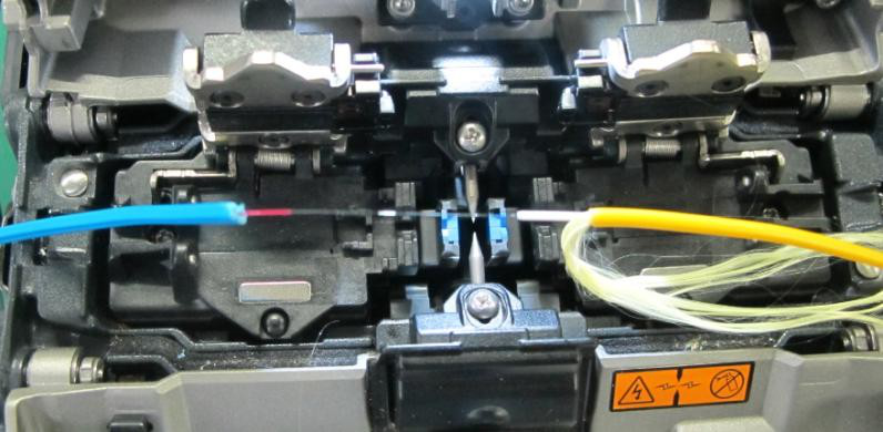
Fusion-splice the optical fiber.
After placing the butterfly-shaped cable and tail cable, close the wind shield of the fusion splicer, and press the SET button to fusion-splice the optical fiber.
After the fusion splicing is completed, open the wind shield, and observe the fusion splicing result. If the optical fiber is smooth, if there is no obvious blister or bulge, and if the optical fiber is not broken after being stretched slightly, the fusion splicing succeeds. Protect the fusion-spliced optical fiber and do not bend it.
-
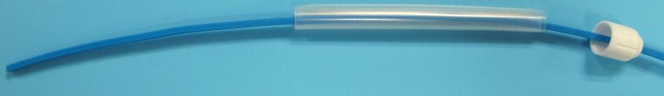
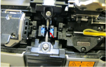
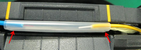
Install the heat-shrinkable sleeve.
-
Push the heat-shrinkable sleeve from one side of the butterfly-shaped cable to the middle of the two optical cables.
Note: Ensure that on the two ends of the sleeve there are about 10 mm outer sheaths of optical fibers inside the sleeve, and the aramid fiber on the tail cable side must be inserted into the heat-shrinkable sleeve.
-
Align the heat-shrinkable sleeve with the length tag line of the fusion splicer, and place the heat-shrinkable sleeve in the heating section.
-
Press the Heating key to heat up the heat-shrinkable sleeve to make it shrink.
-
After the heat-shrinkable sleeve cools and solidifies completely (it usually takes three to five minutes depending on the temperature during construction), take out the optical fiber. The heat-shrinkable sleeve should be completely melted from both ends to the middle. Pull the optical cable gently to check the tensile strength.
Note: Before the heat-shrinkable sleeve cools and solidifies completely, do not pull or move the optical fiber. Otherwise, residual stress will be introduced and the optical fiber will be broken.
You shall use a visual fault locator to check the optical cable. If there is any abnormal light leakage, cut the optical fiber and make a new one.
-
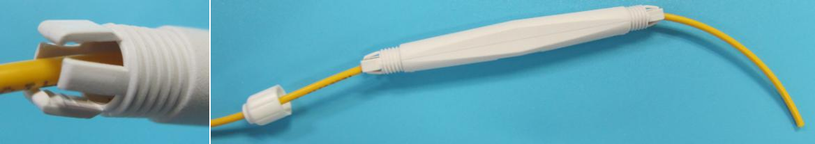
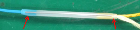
Install the fusion-splicing protective tube.
Push the fusion protective tube onto the heat-shrinkable sleeve. Slightly close the claws on both ends of the tube and tighten the nuts. After the nuts are tightened, the optical cable should be fixed firmly inside the protective tube without sliding. Till now, the optical fiber fusion-splicing is completed.
Note: You should first tighten the nuts on the side of the butterfly-shaped cable to secure this cable.

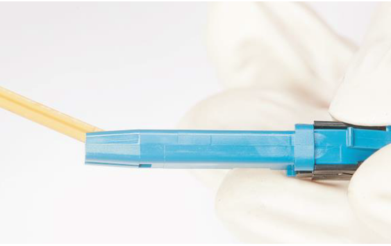
Making a Cold-Connection hybrid cable(Restricted use)
This procedure uses the LC connector of the Shenglongfeng brand as an example to describe how to make an LC connector.
Installing an Optical Fiber Connector
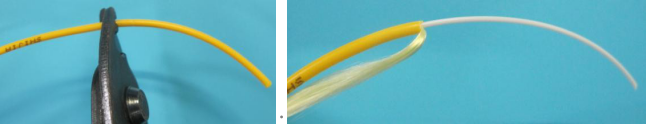
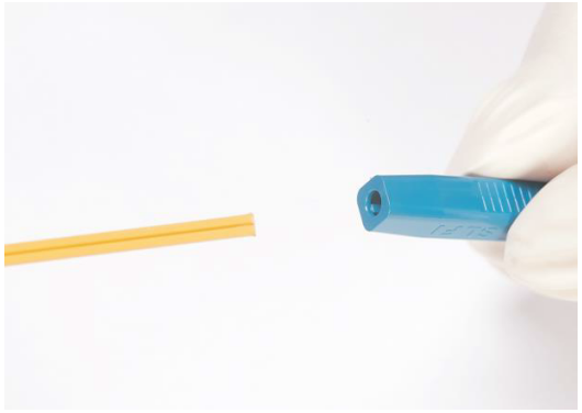
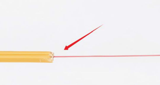
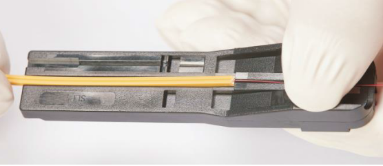
Step 1: Process the optical fiber sheath.
-
Make a sheath cable pass through the round hole first.
-
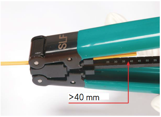
Observe the scale on the fiber stripper, and ensure that the length of the cable with sheath is larger than 40 cm.
-
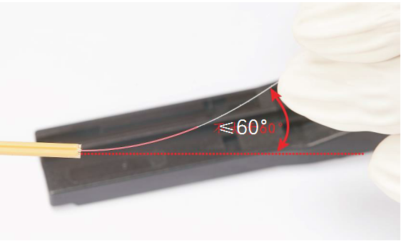
Ensure that the cutting surface is smooth and there is no obvious leakage or bending of the internal steel wires of the optical cable.
-
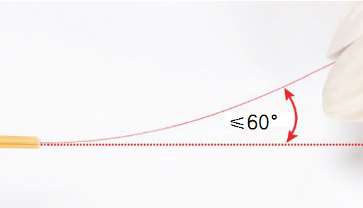
Check the bare fiber, ensure that the angle is not larger than 60°, and repeat the operation three times.
Step 2: Strip the fiber.
-
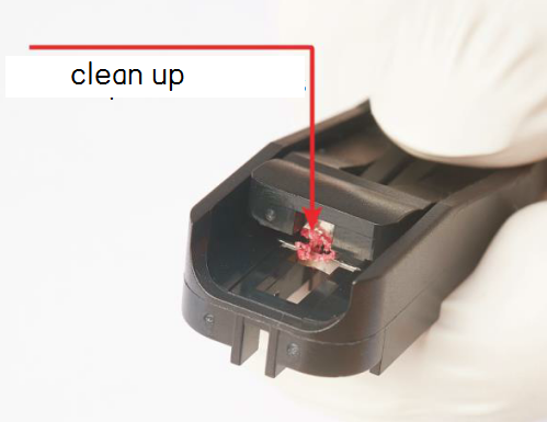
Ensure that there is no foreign object on the edge of the knife. Clean it if there is any.
-
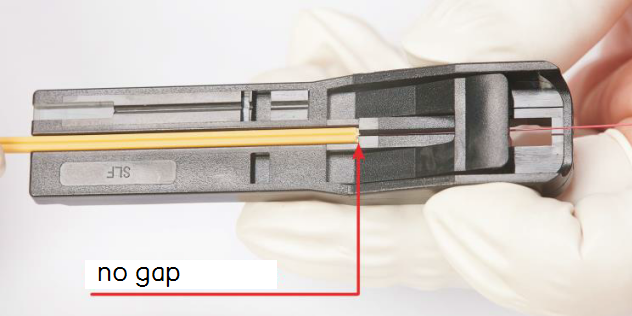
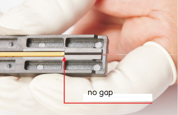
Place the sheath fiber horizontally into the groove, and ensure that there is no gap between the front part of the sheath fiber and the tool.
-
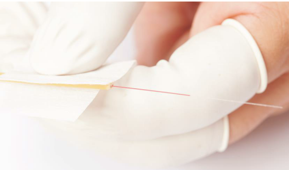
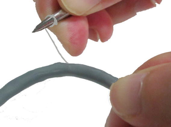
Press down the fiber stripper and pull out the fiber at a constant speed, see the following figure.
-
Remove the coating on the fiber, and keep it for future use.

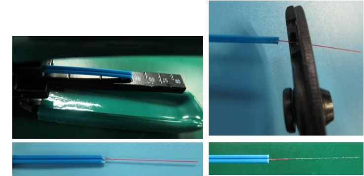
Step 3: Cut the fiber.
-
Check the bare fibers to ensure that the angle is not larger than 60°, and repeat the operation three times.
-
Use an alcohol cotton swab to clean the bare fiber.
-
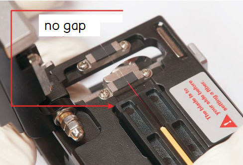
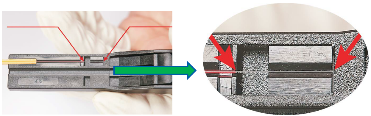
Place the sheath fiber vertically into the groove of the fixed-length tool, and ensure that there is no gap between the front part of the sheath fiber and the tool.
-
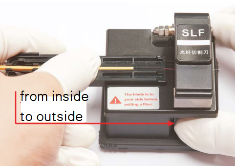
Open the cover plate of the optical fiber cutting knife, and push the ejector lever from the outside to the inside.
-
When installing the fixed-length tool, ensure that there is no gap between the top of the tool and the cutting knife.
-
Close the cover plate, push the ejector lever from the inside to the outside, and cut the optical fiber.
-
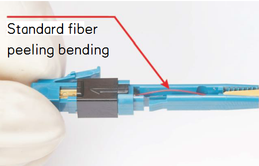
Take the cut optical fiber from the fixed-length tool, and use a standard ruler to measure it. If the fiber meets the standard as shown in the figure, it is qualified.
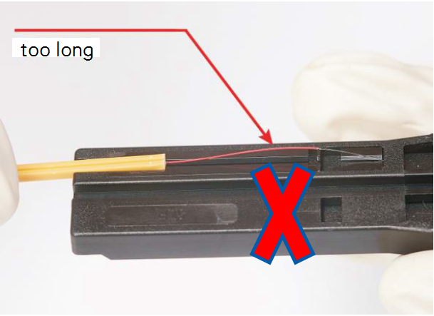
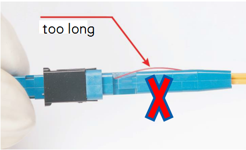
Note 1: If the stripped fiber is too long, the fiber is not qualified and is prohibited to be used in subsequent assembling.
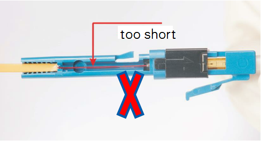
Note 2: If the fiber stripping is too short, the fiber is not qualified and is prohibited to be used in subsequent assembling.
Step4: Assemble the optical fiber.
Note:
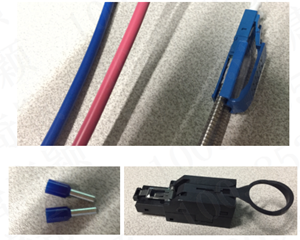
When the fiber is inserted into the optical module:
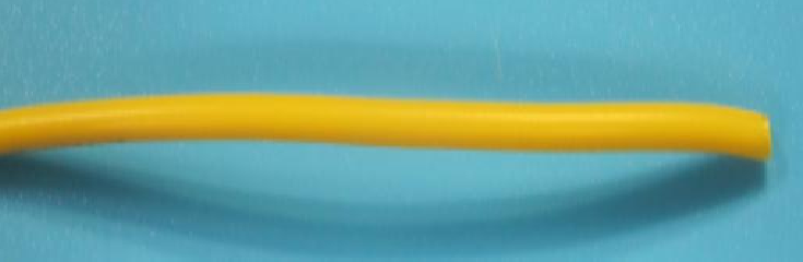
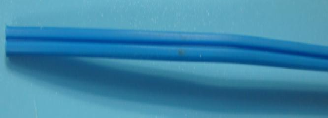
The TX at the PB end corresponds to the optical fiber in the yellow butterfly-shaped cable, and RX corresponds to the optical fiber in the blue butterfly-shaped cable.
The TX at the QCell end corresponds to the optical fiber in the blue butterfly-shaped cable, and RX corresponds to the optical fiber in the yellow butterfly-shaped cable.
-
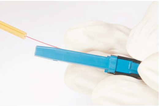
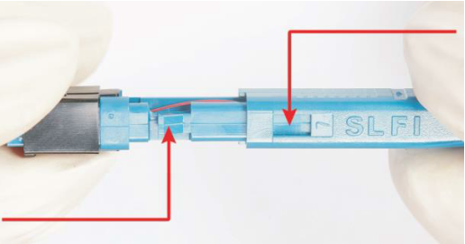
Insert the sheath fiber into the V slot at an angle of 30° with the LC.
-
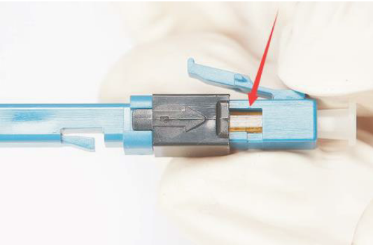
Push the sheath fiber to the positioning block, and then press it into the tail clamp slot. Push the sheath fiber to ensure that the top of it is against the positioning block in the tail clamp slot.
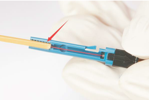
-
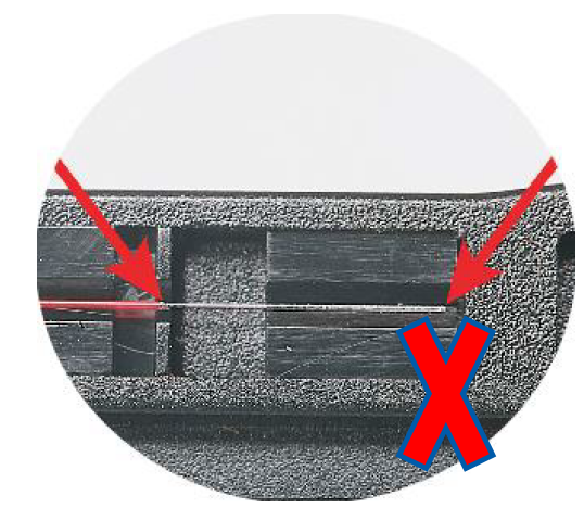
After the above operations are completed, bend the fiber slightly. It is recommended that the bent fiber does not exceed the top edge of the tail clamp slot. If the stripped fiber is too long or too short, it is prohibited to be assembled, and you must strip the optical fiber again.
Note:
If the stripped fiber is too long or too short, it is prohibited to be assembled, and you must strip the optical fiber again.
-
Close the tail sheath, and ensure that the square window aligns with the main latch. If you hear a click, it indicates that the tail sheath is closed properly.
-
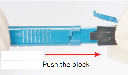
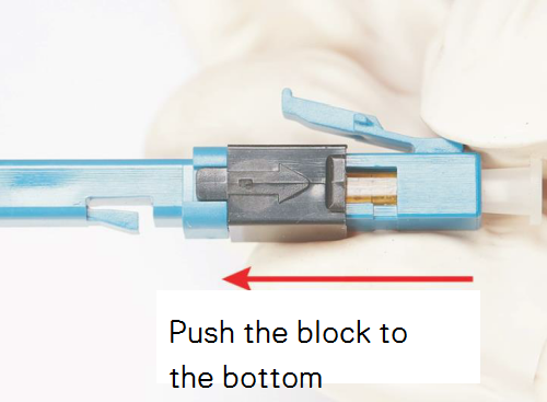
Push the black block in the direction of the arrow until it reaches the top, and secure the optical fiber.
-
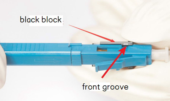
Remove the black block along the front groove.
-
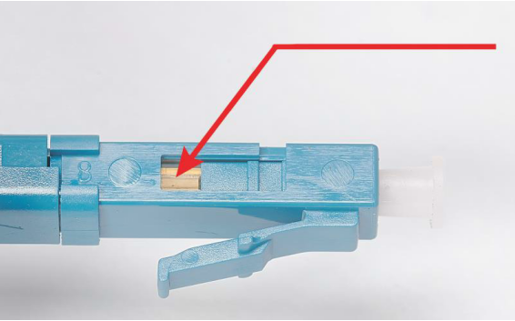
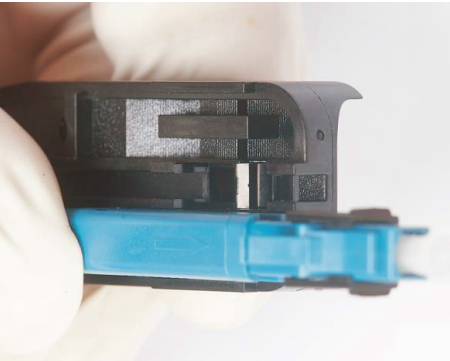
Ensure that the small window on the LC is completely closed.
Removing an Optical Fiber
-
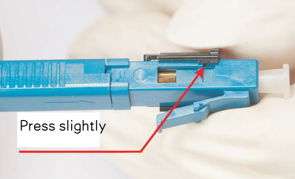
Press the black block slightly into the two grooves on the front side of the LC.
-
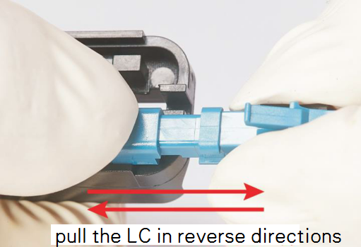
Install the tail sheath of the LC to the disassembly block position of the tail sheath of the fixed-length tool.
-
Press it, and then use two hands to pull the LC in reverse directions to extract the tail sheath.
-
Push the black block to the bottom in the direction of the arrow.
-
Ensure that the small window on the LC is completely opened.
-
Pull out the sheath fiber at an angle of 30° with the LC.
Making a 2-Core RJ45 Power Connector of a hybrid cable
Tools and Materials
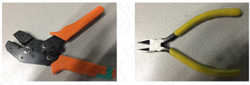
Required tools:
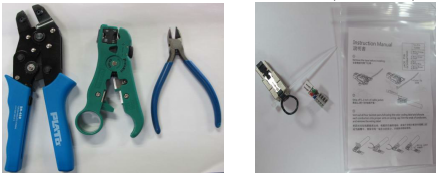
a tubular-terminal crimping pliers (at least three types: 1.5 mm2, 2.5 mm2, and 4 mm2), a fiber stripper, a diagonal pliers, and a flathead screwdriver.
Required materials:
two-core RJ45 power connectors, round tubular terminals, and hybrid cables (preprocessing: at least 30 cm of the outer sheath and filling rope is removed). Note: The power cable must pass through tubular terminals. Otherwise, it may cause poor contact and safety risks.
Steps:
-
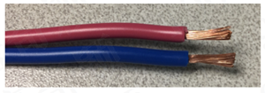
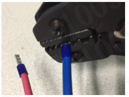
Peel off the cable and pass it through the tubular terminals. Use the fiber stripper to strip off the insulation protective tube of the power cable. The length stripped off is the same as that of the tubular terminal. Screw the wires into strands, and insert them into the tubular terminals.
-
Crimp the wires. Use the crimping pliers to crimp the tubular terminals, and use the diagonal pliers to remove redundant wires from the front end.
-
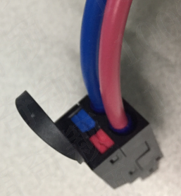
Install the terminals. Insert the crimped terminals into the corresponding jacks of the two-core RJ45 power connector in accordance with the color. After you insert a terminal into the position properly, you can hear a click sound. Then, gently pull the power cable outwards until the terminals do not move in the connector, which indicates that the test is completed. Otherwise, you need to push the terminals to the position and try again.
-
(Optional) Remove the terminals. Align a flathead screwdriver with the flathead slot in the middle of the color block of the power connector, press the slot, and gently pull the cable to pull the terminals out.
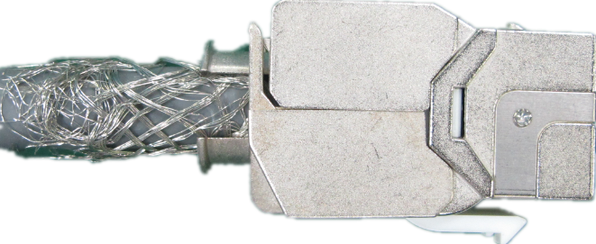
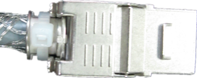
Making a CAT6A Industrial Registered Jack (RJ)
Note: CAT6A industrial RJ must be purchased from ZTE corporation, it’s a customized material of ZTE.
Preparation:
Required tools:
a crimping pliers (tubular terminal crimping pliers without the crimping end, delivered with the CAT6A industrial RJ), a wire stripper, and a diagonal pliers.
Required materials:
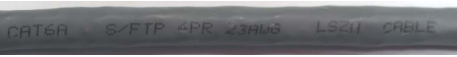
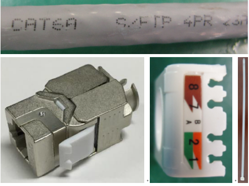
a CAT6A industrial RJ (with a threading device) and a CAT6A S/FTP network cable.
Steps:
-
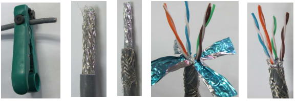
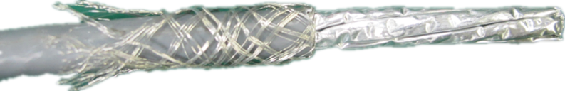
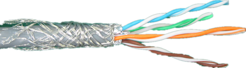
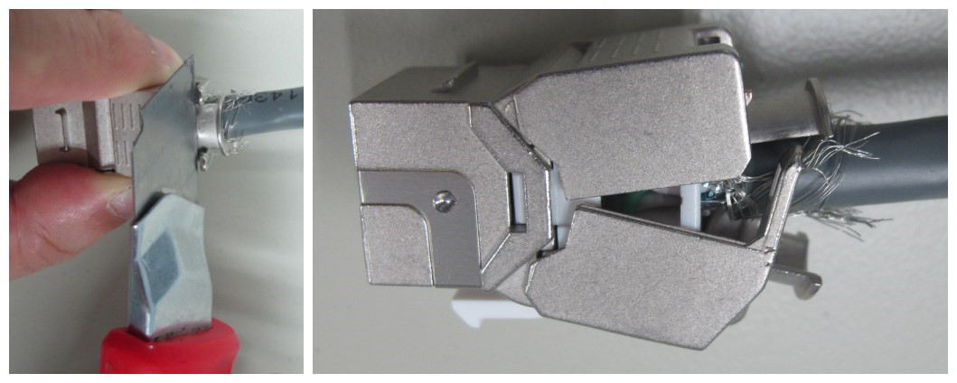
Peel off the cable. Use the wire stripper to remove about 30 mm outer sheath of the network cable, and turn the braided shielding over to the outer sheath of the tail. Open the aluminum foil shielding, and use the diagonal pliers to remove it along the root.
-
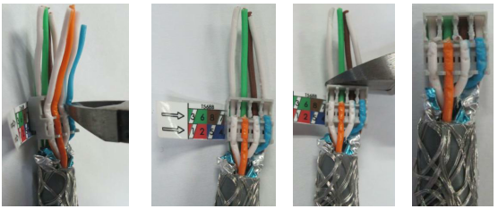
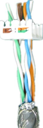
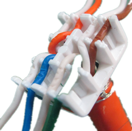
Crimp the cable. Thread the four cores (in white-green, green, brown, and white-brown respectively) into the bottom jack of the threading device in accordance with the color sequence specified for the threading device of the industrial RJ. Push the threading device to the end of the core, and then press the four cores (in white-orange, orange, white-blue, and blue respectively) into the slots on the outer layer of the threading device. Tighten them with your fingernails.

-
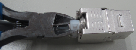
Cut the cable. Use the diagonal pliers to cut the four cores (in white-orange, orange, white-blue, and blue respectively) along the edge of the threading device, cut the other four cores (in white-green, green, brown, and white-brown respectively) along the outer protective sheath of the cable, and then tear off the color indication labels.
-
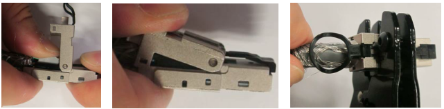
Crimp the RJ. Turn over the outer protective sheath of the industrial RJ, and install the end, on which you can see the cores, of the threading device into the slot of the industrial RJ. Ensure that the direction of the threading device is correct. Slight push the threading device until the threading device cannot move, turn over the upper cover and gently press it. Then, use the crimping pliers to slowly increase the force until the upper cover is pressed in position.
-
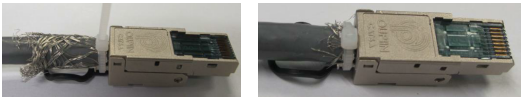
Secure the RJ. Use the delivered ties to fasten the spring at the end of the outer protective sheath of the cable, and trim the braid shielding neatly. The installation is completed.
-
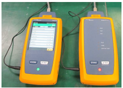
Check the cable performance. Use a dedicated network cable tester, such as the fluke DSX-1800, to test the performance of the network cable crimped at both ends. The network cable must pass the CAT6A Channel (+POE) test specified in the TIA 568 C.
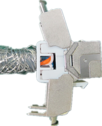
Making a CAT6A Female Connector
Preparing Materials and Tools
Materials preparation
The materials needed include: CAT6A S/FTP network cables and CAT6A modules (including line cards and cable ties).
Tools preparation
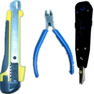
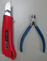
The tools needed include a wire stripper or a utility knife, a pair of diagonal pliers, and a cable-clamping knife (optional).
Making a Network Cable
-
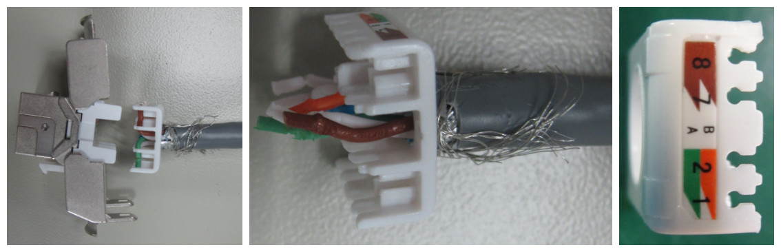
Strip off a cable. Use a knife to strip off the sheath of a network cable for over 40 mm. Turn over the braided shield to show the network cable. Open aluminum foil of all twisted pair cables and cut off it from the bottom.
-
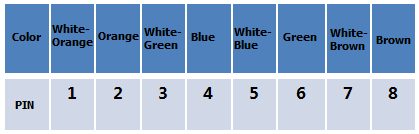
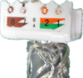
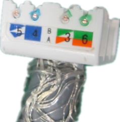
Thread the cable. Thread the four pairs of twisted pair cables in two groups through the corresponding holes in accordance with the TIA 568 B color marks on the line card.
-
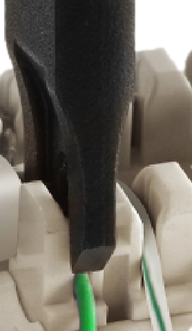
Clamp the cable. Straighten each core of the twisted pair cables, and use a cable-clamping knife or your hand to fix the cores into the corresponding slots in accordance with the TIA 568 B color marks on the line card. The line sequence is as follows:
-
Cut off the cable. Use a pair of diagonal pliers to cut off the cores outside the line card, and then verify that the line sequence is the same as the TIA 568 B color marks on the line card.
-
Lock the module. Insert the line card into the main part. Make sure that they are in the same direction; otherwise, rotate the line card 180° before inserting it into the main part. Push the white line card into the main part until there is about 1/5 of the space left inside, and tightly lock the upper cover and lower cover. You can hear a click when the module is locked properly. Then, cut off the shield cable left outside.
-
Secure the registered jack. Use the self-contained cable ties to tie the upper cover and lower cover securely, and remove redundant ties. The installation is completed.
-
Check the network cable. Insert the self-contained one-meter-long CAT6A jumper into the front of the module, and conduct measurement on the fluke device. It is required that the TIA 568B CAT6A channel measurement requirements must be satisfied.
Remove a module (for troubleshooting or reuse purposes)
-
Tools: a utility knife and a pair of diagonal pliers.
-
Use a pair of diagonal pliers to cut off the fixing part of the cable ties, and remove the cable ties.
-
Use a utility knife to prize the two release latches on the metal shell. The shell is opened automatically. Make sure that you do not use too much force; otherwise, the release latches may be distorted and cannot be used.
-
Drag the network cable to unplug the line card, use the diagonal pliers to separate the cores from the line card slot, and pull out the network cable. The module is removed successfully.
Making a CAT5e Network Cable
Preparing Materials and Tools
Materials preparation:
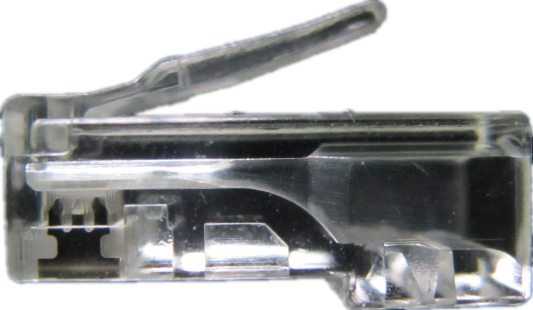
The materials needed include: a CAT5e network cable (with a CAT5e mark on the cable) and CAT5e registered jacks.
Tools preparation:
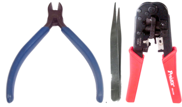
A pair of diagonal pliers, a pair of tweezers, and a pair of network cable crimping pliers.
Making a Network Cable
Note: It is prohibited to use a pair of network cable crimping pliers to cut off the outer layer of the network cable; otherwise, the cores of the network cable may be damaged.
-
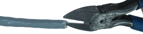
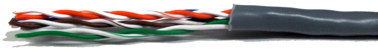
Strip off a cable. Use a pair of diagonal pliers to cut a 10-mm hole on the outer layer of the network cable to show nylon thread.
-
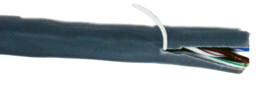
Hold the network cable tightly, wind the nylon thread around a pair of tweezers and tear the outer layer for about 20 mm, and use the diagonal pliers to trim the outer layer.
-
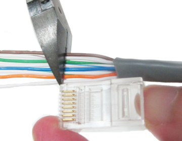
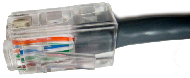
Straighten the cores in accordance with the TIA/EIA-568B standard (white/orange-orange-white/green-blue-white/blue-green-white/brown-brown), and use the diagonal pliers to cut off the cores so that the exposed cores are 14–15 mm long. You can use a registered jack for length reference.
-
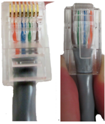
Straighten up the cores. Insert the trimmed cores into a registered jack, and make sure that the line sequence observed from the spring side is the same as that specified in the standard.
Note: Each hole on the registered jack is inserted with a core down to the bottom. You can check whether a core is inserted properly by observing it from the spring side. The length of the outer layer inside the registered jack is about 8 mm.
-
Insert the registered jack into the RJ45 hole of the crimping pliers, and hold the end of the network cable to prevent the registered jack from loosening by keeping certain pressure. Press the handles with force for five seconds. It is recommended that you press the handles again to guarantee the crimping effect.
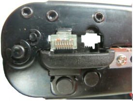
-
Verify that the registered jack is made properly.
-
Use a dedicated network cable detection device (for example, fluke) to check the network cable to verify that the network cable satisfies the TIA 568B CAT5e Channel standard.