
PB1124F Bridge Installation Guide

The pBridge (PB) is not water proof. Do not install the device in a wide scenario that is subject to rain, such as a courtyard. Otherwise, the device may be corroded by water and damaged permanently.
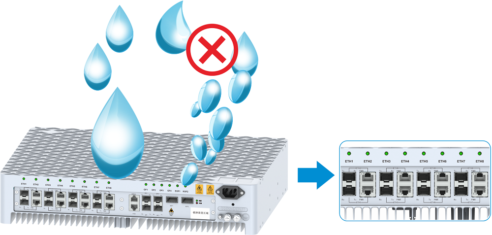
A waterproof bend is required for the network cable at the pBridge side. Avoid the risk of rain or condensate from the air conditioner getting into the pBridge along network cables. Otherwise, the network ports may be corroded and the equipment may be permanently damaged.

When the PB is installed on the wall, the interface of the PB must face downwards, cannot face other directions. Otherwise, water or dust may enter the Ethernet interface and cause the equipment to be damaged permanently.
Do not place the device on a flat surface without fixing the device. Otherwise, the device may be damaged by overheat.
Do not install the PB in a position where there is a direct heating body underneath.
The device serial number must be written on a device. The device serial, such as PB-1, must be the same as that on the design label.
The fiber connections must be the same as the design draws. Otherwise, the front end and the back end may not be consistent with each other, and the PB cannot be properly commissioned.
Do not place any item on the PB equipments.
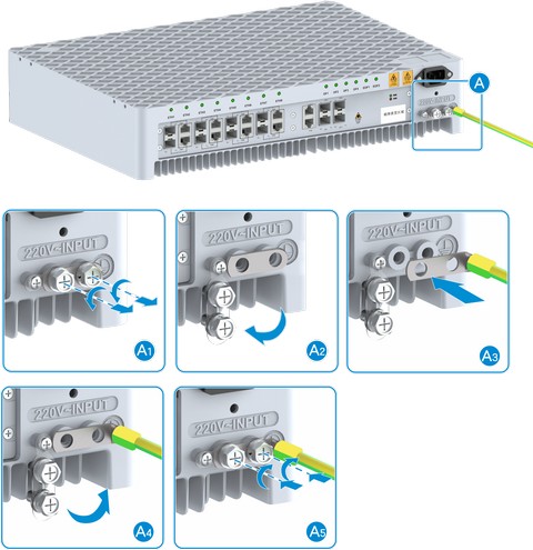
The PB must be installed with the grounding cable.
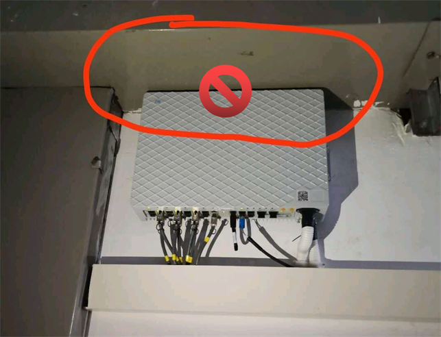
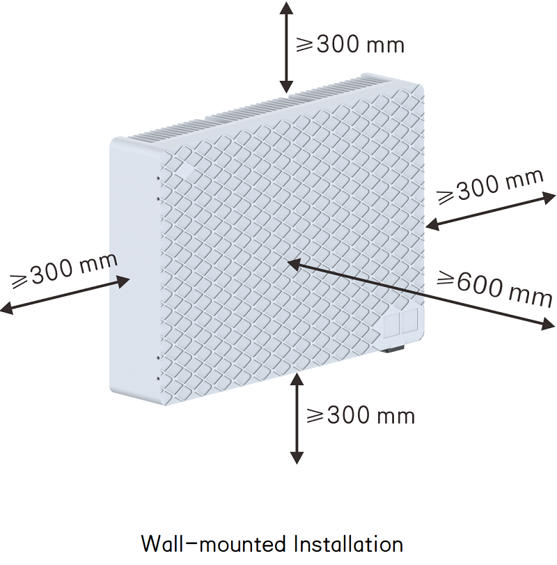
When a PB is installed on a wall or a pole, a space of more than 300 mm must be reserved at the top.
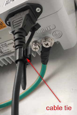
After the power cable is installed, you shall fasten it with the dedicated cable tie to prevent it from falling off.
To prevent burn injuries, power off the device and wait 10 to 15 minutes before removing the device.




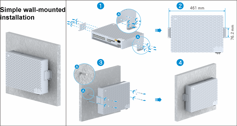

Simple wall-mounted installation:
Install the two flanges in the middle holes on both side of the PB to ensure symmetrical balance.
The heat dissipation teeth should face the wall, and the smooth surface is face outwards.
The ports must face downwards to prevent the dust from getting inside.
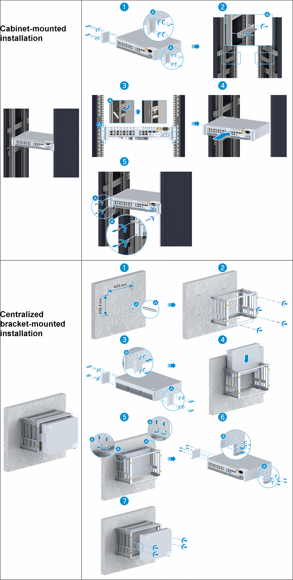
Cabinet-mounted installation:
The PB1124F has an automatic fan and does not need any additional heat dissipation fans.
The radiating fins should face downwards and the plain side should face upwards.
No heating body should be placed directly under a PB. An interval of at least 1U should be reserved.
A height of 2U must be provided in a 19-inch standard cabinet.
The cabinet depth should be at least 480 mm.
Install flanges on both sides of the PB through the holes close to the interface board side, and install brackets on both sides of the PB through the middle holes as holders.
Check whether there are supporting rails at the installation points. If there is no supporting rails, install the rails.
Centralized bracket-mounted installation:
A maximum of three PBs can be installed. Install two PBs vertically and install one PB on the front side.
The ports should face downwards.
The radiating fins should face inwards and the plain side should face outwards.

The cables of PB1124F include:
PB power cable: Finished AC power cable
Grounding cable: 6 mm2yellow-green grounding cable.
Uplink interface optical fiber: LC-LC optical fiber, connected to VBP OF optical interface or OF4 of upper-level cascaded PB.
Downlink interface optical fiber: LC-LC optical fiber, connected to the OF1 of the lower cascaded PB.
Fan power cable: Connected to the FAN interface to supply power to the fans at the bottom of the PB.
Ethernet cable: The PB has 8 ETH interfaces for connecting to a pRRU through hybrid cables.
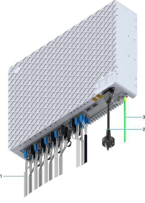
1. PB1124F power cable installation

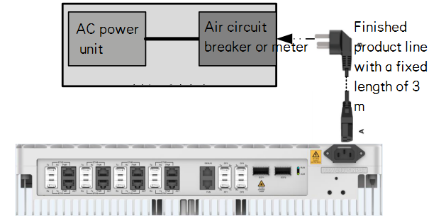
Note:
By default, a 3 m finished 3-core AC power cable is delivered to a PB and connected to the nearest device.
If the distance between a PB and an AC power supply module exceeds 3 m, the customer needs to provide an air circuit breaker or a meter. The specific power supply solution shall be provided by the design institute.
Do not use two-core DC power cables for PB power supply link. The grounding cable of the three-core AC power cable should be indirectly grounded.
The AC power cable cannot be directly connected.
When making the power cable of the photoelectric composite cable, cut the connector and install the tubular terminal. When making the grounding cable of the equipment, install the OT terminal.

Tubular terminal

OT terminal
2. Optical Fiber Connection

|
Scenario |
Side A |
Side B |
|---|---|---|
|
VBP—PB Optical Fiber |
VBP OF port |
PB OF1 port |
|
PB cascading |
PB OF1 port |
PB OF4 port |
|
MAU—PB Optical Fiber |
OF_PB port of CFS |
PB OF2 port |
3. Ethernet cable


Note:
The 1.5 mm2 hybrid cable supports a maximum distance of 200 m.
CAT6A network cable supports a maximum distance of 100 m. But consider the engineering restriction, we suggest the length of cable <= 80 m.
4. PB1124F grounding

Note:
The PB grounding cable is the 6 mm2 yellow-green protective grounding cable.
© ZTE Corporation All Rights Reserved