For the installation kits, refer to the following table.
| Component | Quantity | External View |
|---|---|---|
| L-shaped part | 1 |  |
| Sheet-metal mounting plate | 1 |  |
| Butterfly nut and washer | 2 |  |
| M5 × 30 pan-head screw | 2 |  |
The installation steps are as follows:
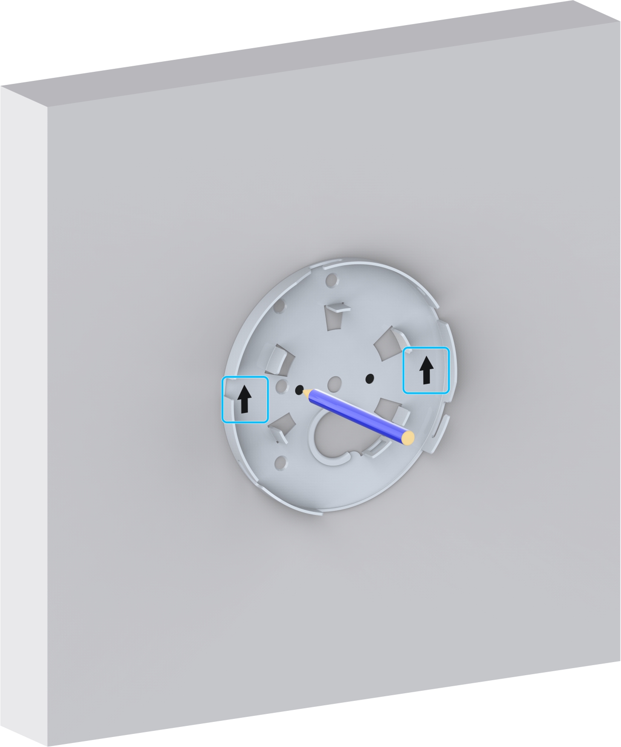
1. Drill two installation holes and one cable hole on the ceiling that is removed.
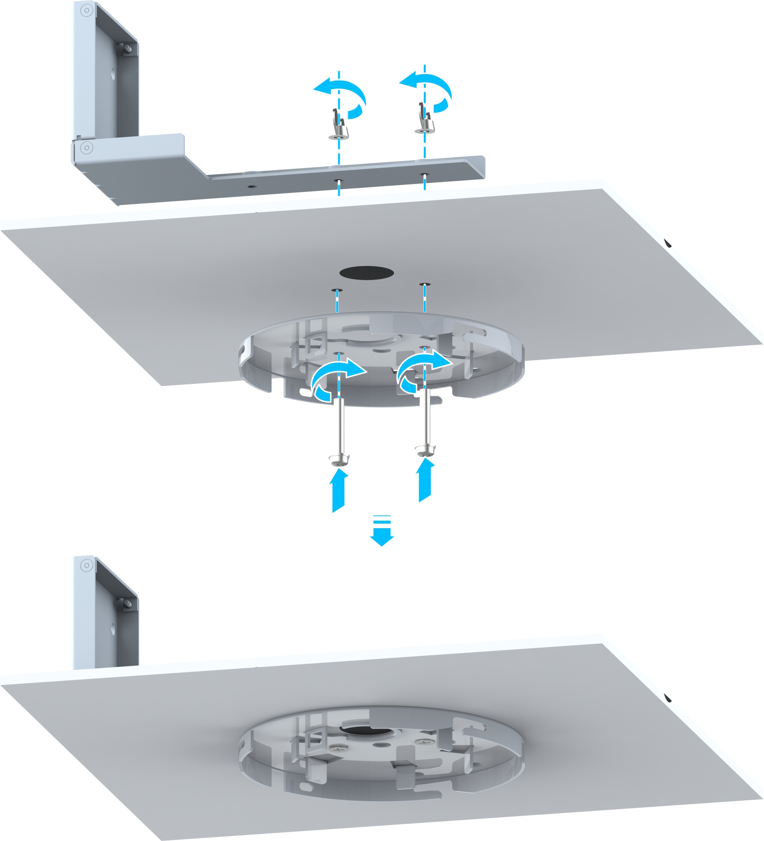
2. Place the L-shaped part on the ceiling and thread two screws through the ceiling. Install the sheet-metal mounting plate onto the ceiling, and tighten the screws with a torque of 3 N·m.
3. (Optional) Install the optical module.

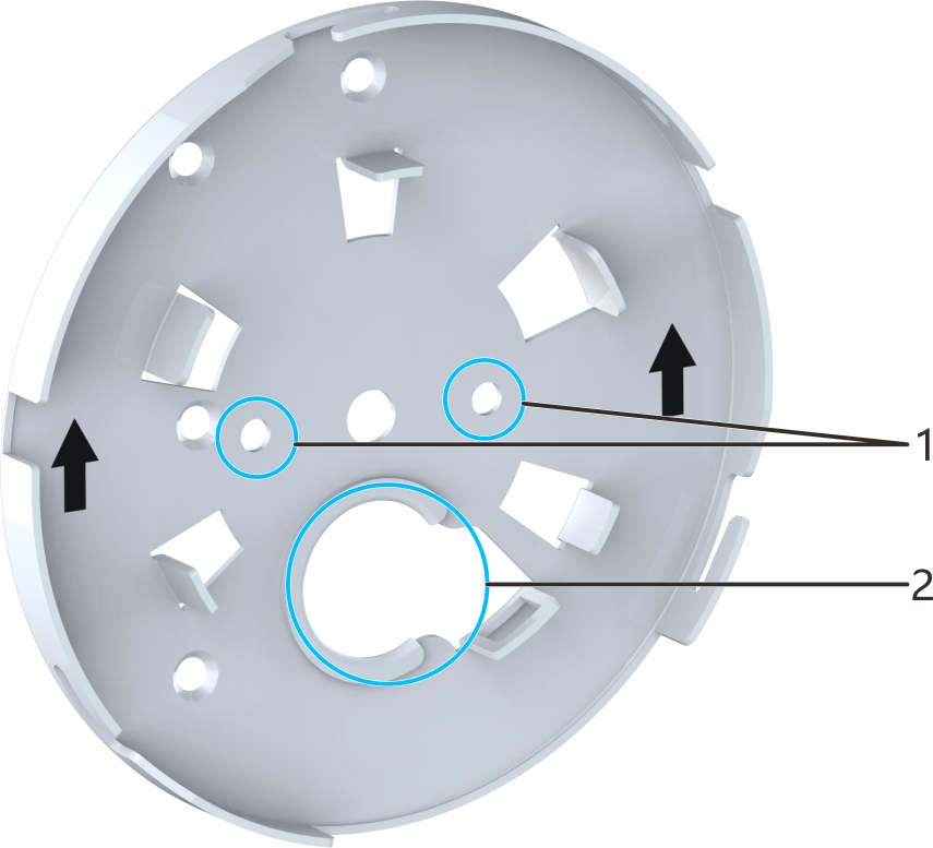
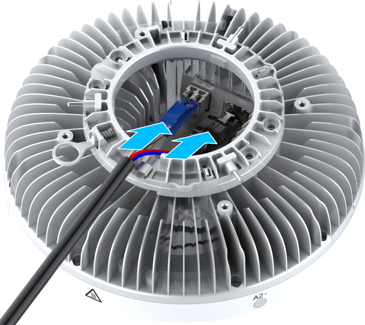
4. Pass the Hybrid cable connector through the cable hole on the sheet-metal bracket, and connect it to the Tx/Rx interface and PWR interface of the Pico RRU.
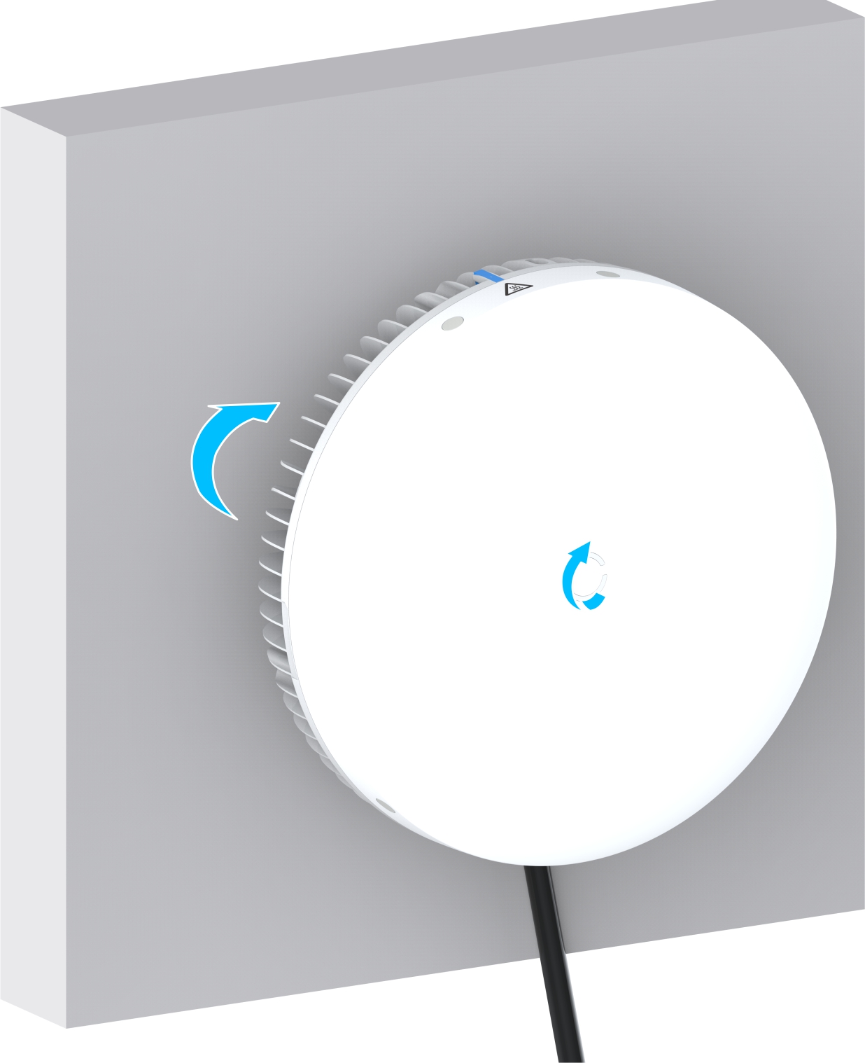
5. Mount the device installed with the mounting assembly to the L-shaped slot of the sheet-metal mounting plate, twist the device into the top of the L-shaped slot until you hear a click of the latch.
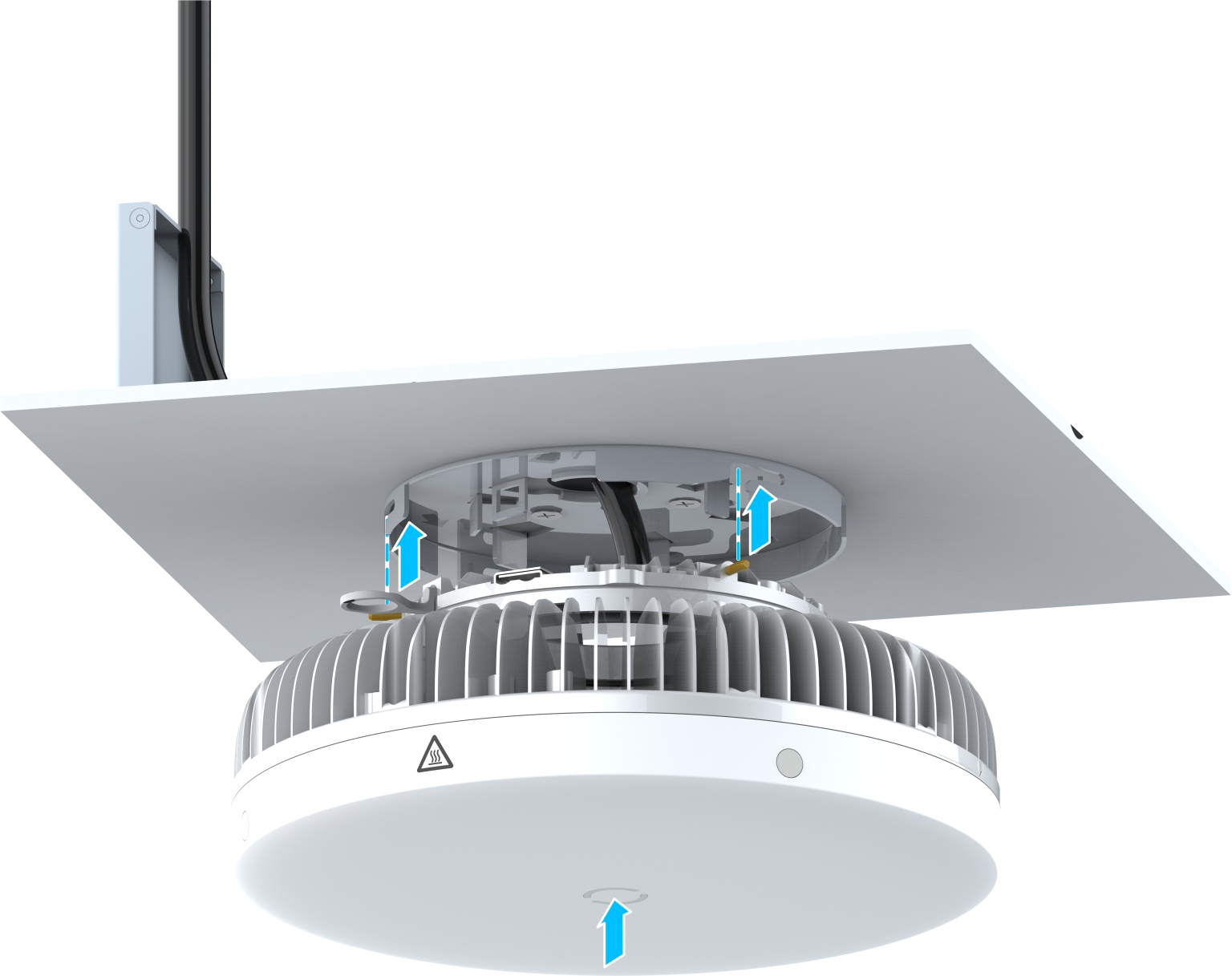
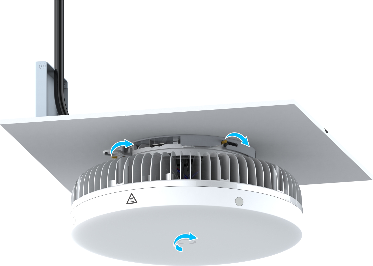
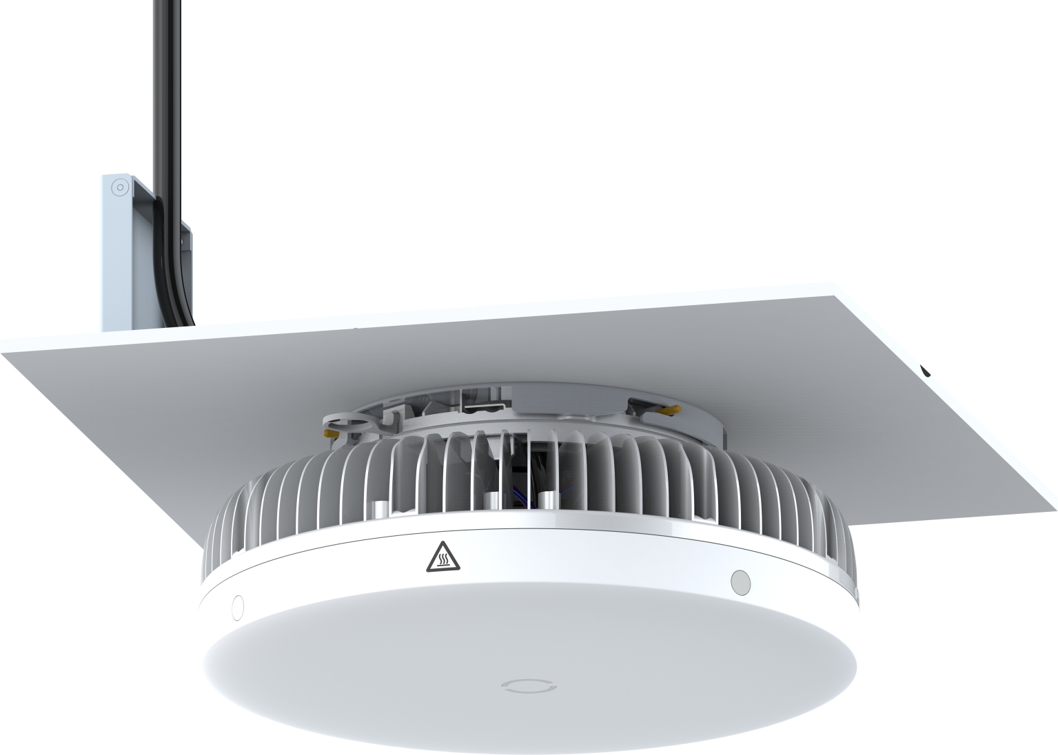
The following figure shows the device mounted on the ceiling.
For the installation kits, refer to the following table.
| Component | Quantity | External View |
|---|---|---|
| Sheet-metal mounting plate | 1 |  |
| M5×35 self-tapping screw | 2 |  |
| φ6×30 expansion tube | 2 |  |
The installation steps are as follows:
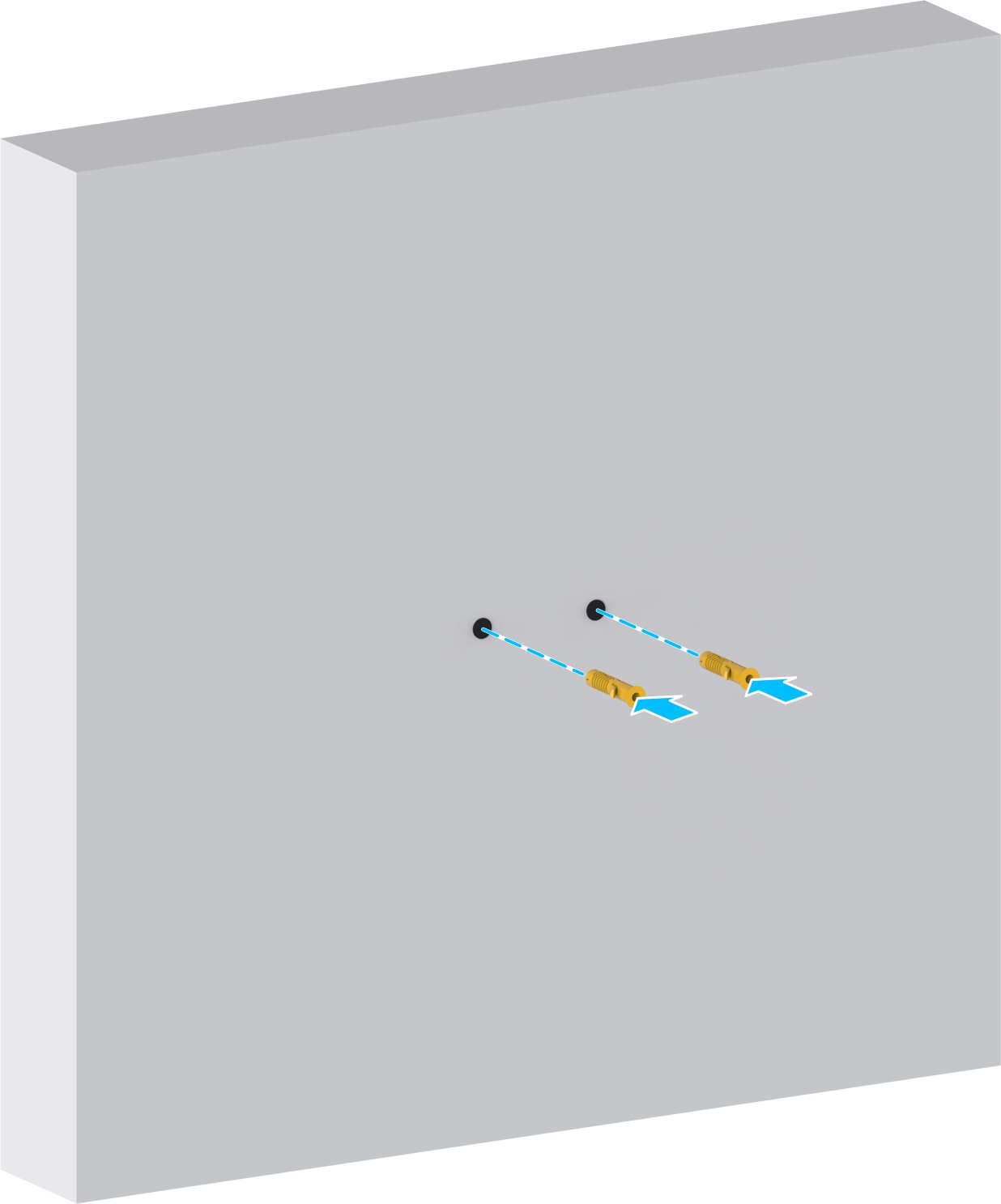
1. Use an electric percussion drill to make two holes on the cement wall.
2. Use a rubber hammer to knock the expansion tubes into the holes on the wall.
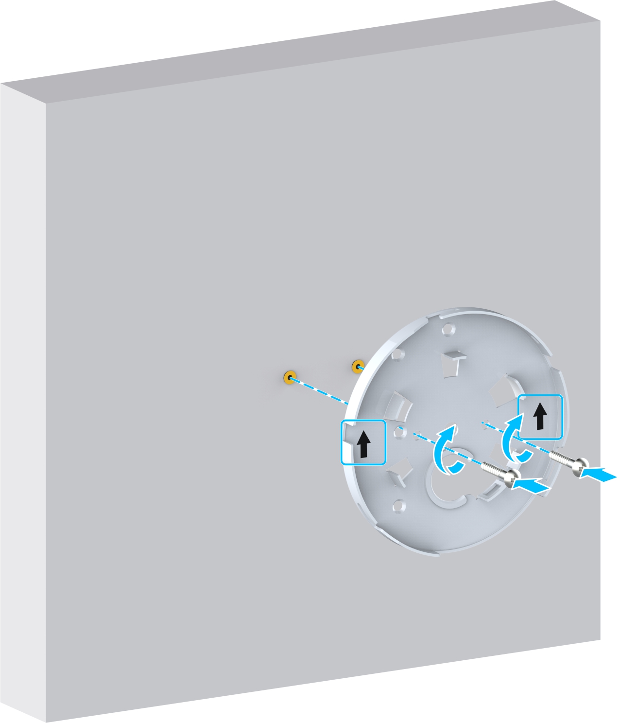
3. Use two self-tapping screws (with expansion tubes) to fix the sheet-metal mounting plate on to the wall.
4. (Optional) Install the optical module.

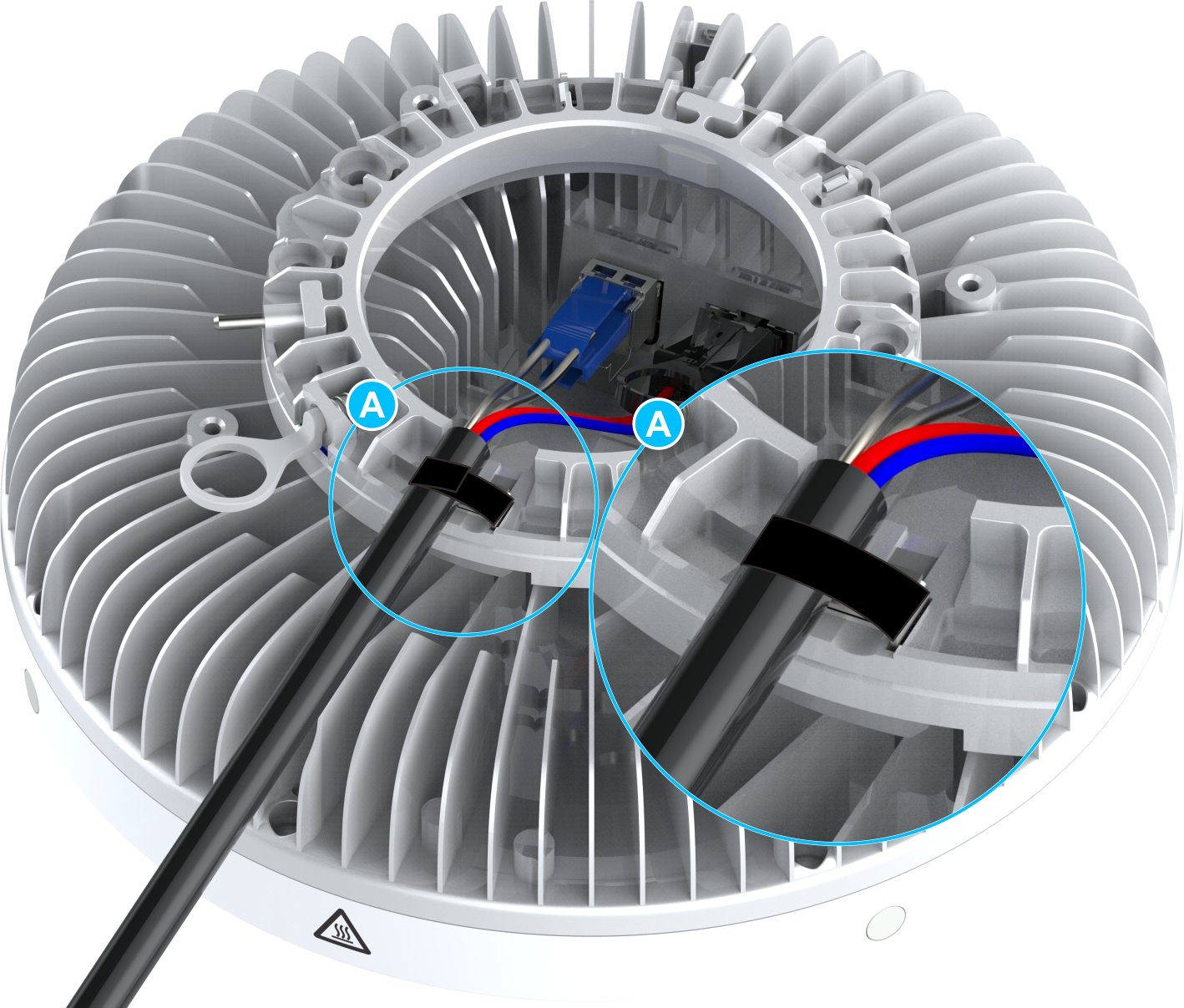
5. Connect the connector of the Hybrid cable to the Tx/Rx and PWR interfaces of the Pico RRU,

6. Secure the Hybrid cable by using the Velcro on the Pico RRU base,
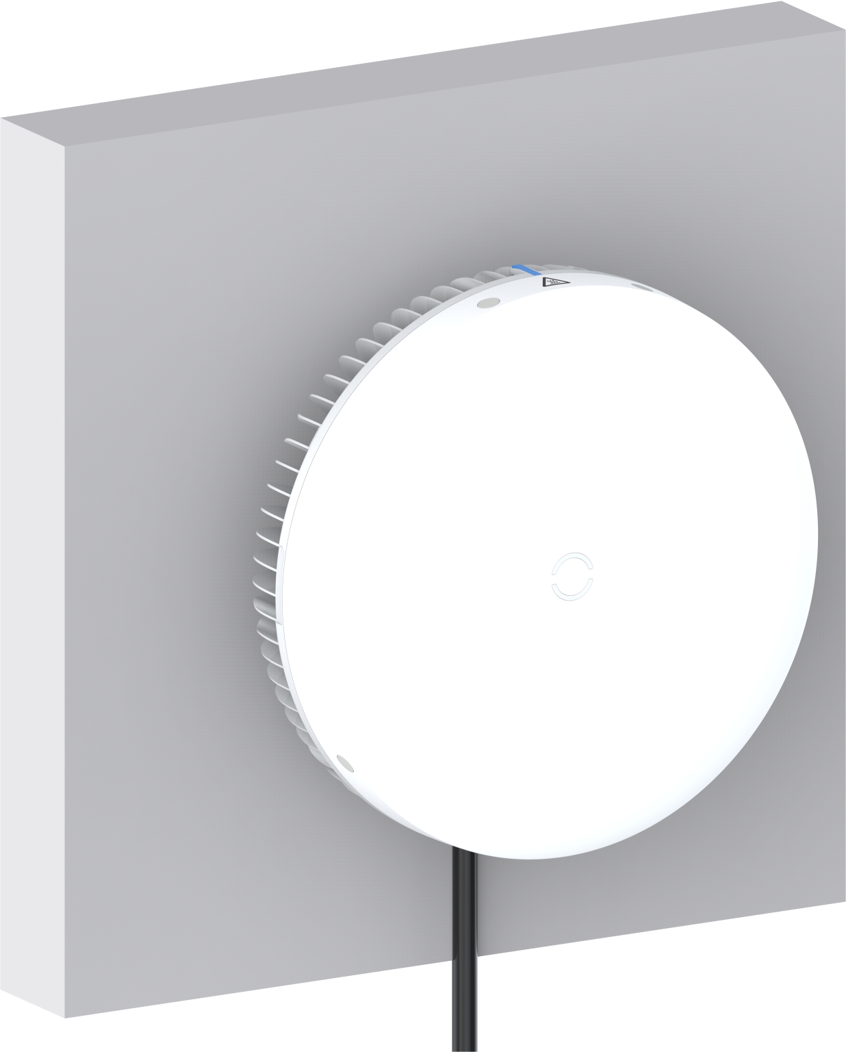
7. Mount the device installed with the mounting assembly to the L-shaped slot of the sheet-metal mounting plate, twist the device into the top of the L-shaped slot until you hear a click of the latch.
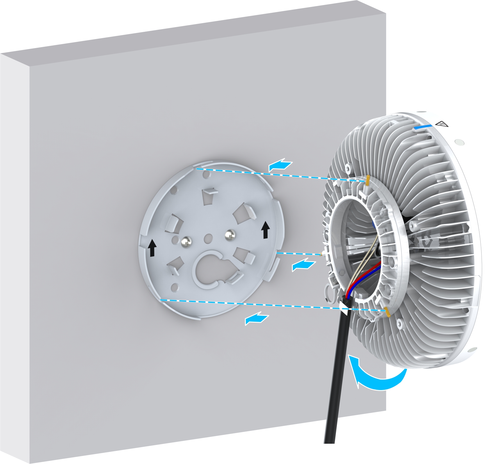
The following figure shows the device mounted on the wall.
For the installation kits, refer to the following table.
| Component | Quantity | External View |
|---|---|---|
| L-shaped part | 1 |  |
| Fasteners | 2 |  |
| M5×50 cross pan-head screw | 4 |  |
| Sheet-metal mounting plate | 1 |  |
| Butterfly nut and washer | 2 |  |
| Non-slip pad | 2 |  |
| M5×30 cross pan-head screw | 2 |  |
The installation steps are as follows:
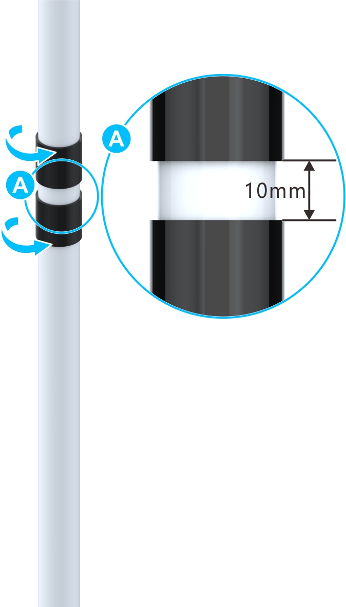
1. Wrap a pole with two non-slip pads with adhesive on the back.
2. Install the L-shaped parts on the vertical pole with a torque of 3 N·m.
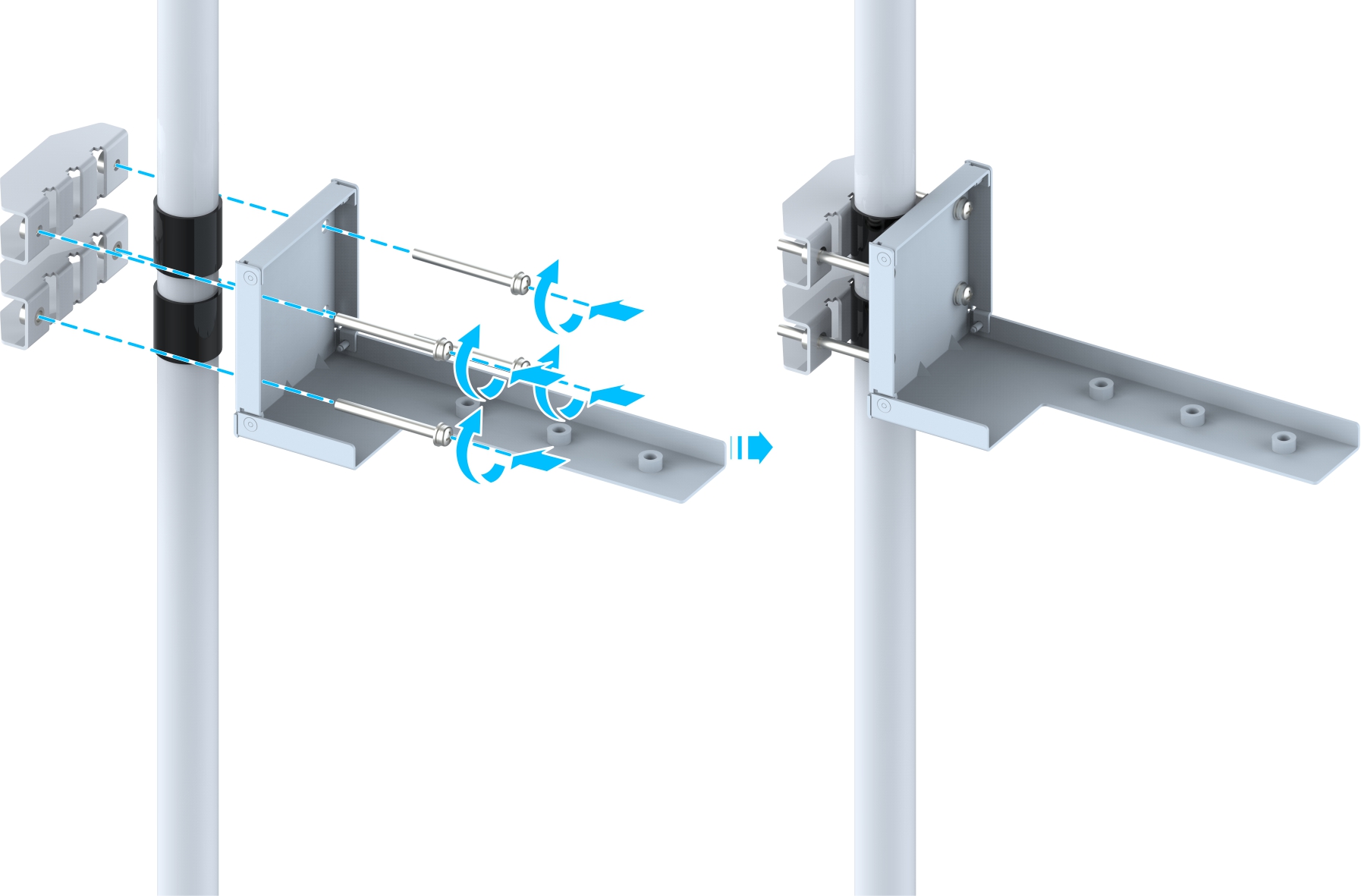
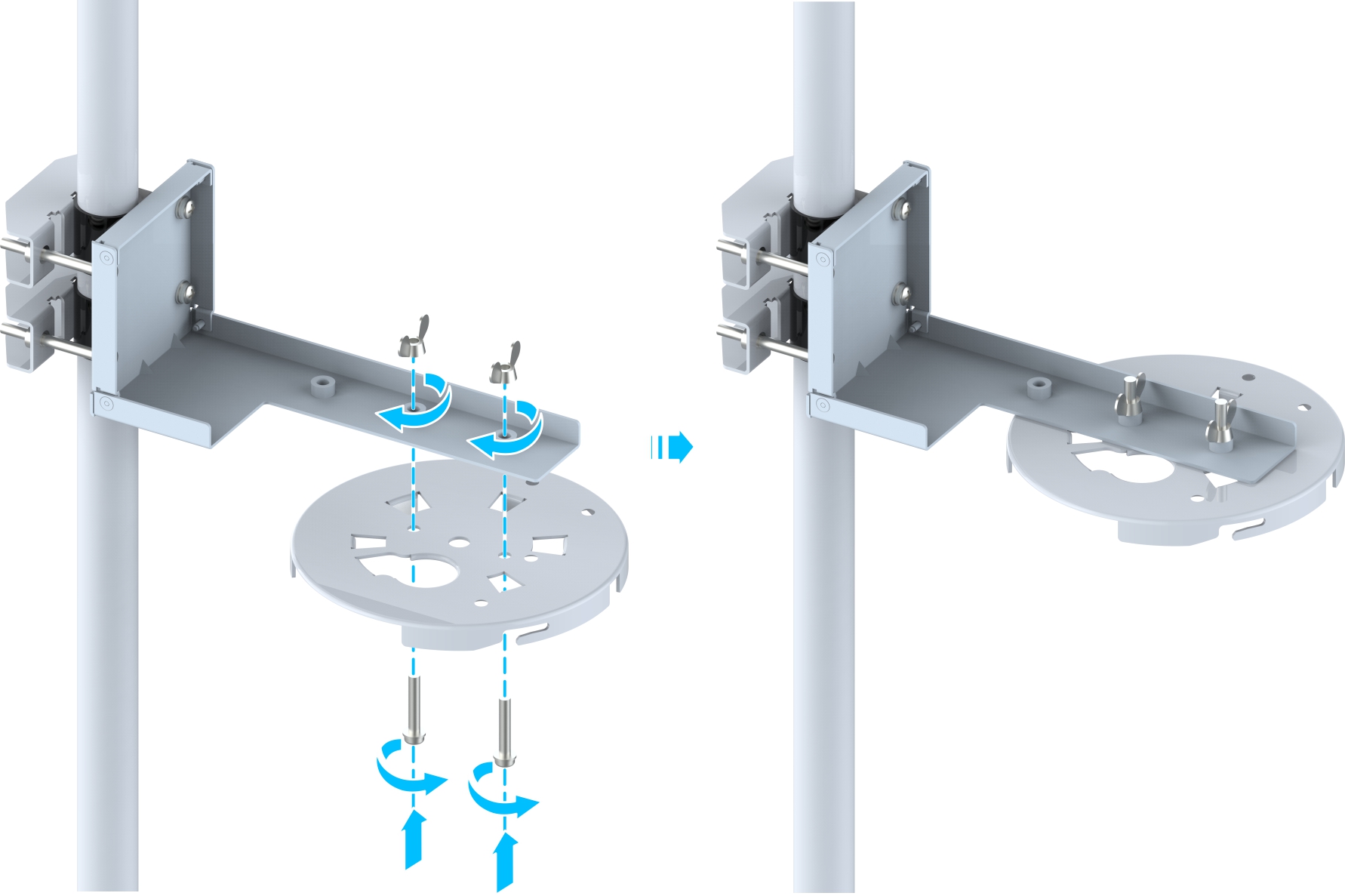
3. Fix the sheet-metal mounting plate onto the L-shaped component with two M5 × 30 cross pan-head screws, and tighten the screws with a torque of 3 N·m.
4. (Optional) Install the optical module.
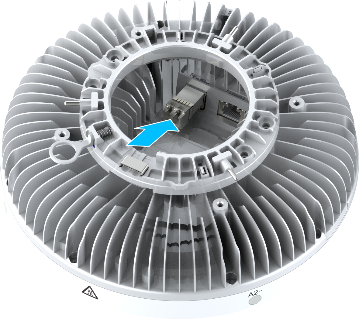
5. Pass the Hybrid cable connector through the cable hole on the sheet-metal bracket, and connect it to the Tx/Rx interface and PWR interface of the Pico RRU,.

6. Mount the device installed with the mounting assembly to the L-shaped slot of the sheet-metal mounting plate, twist the device into the top of the L-shaped slot until you hear a click of the latch.
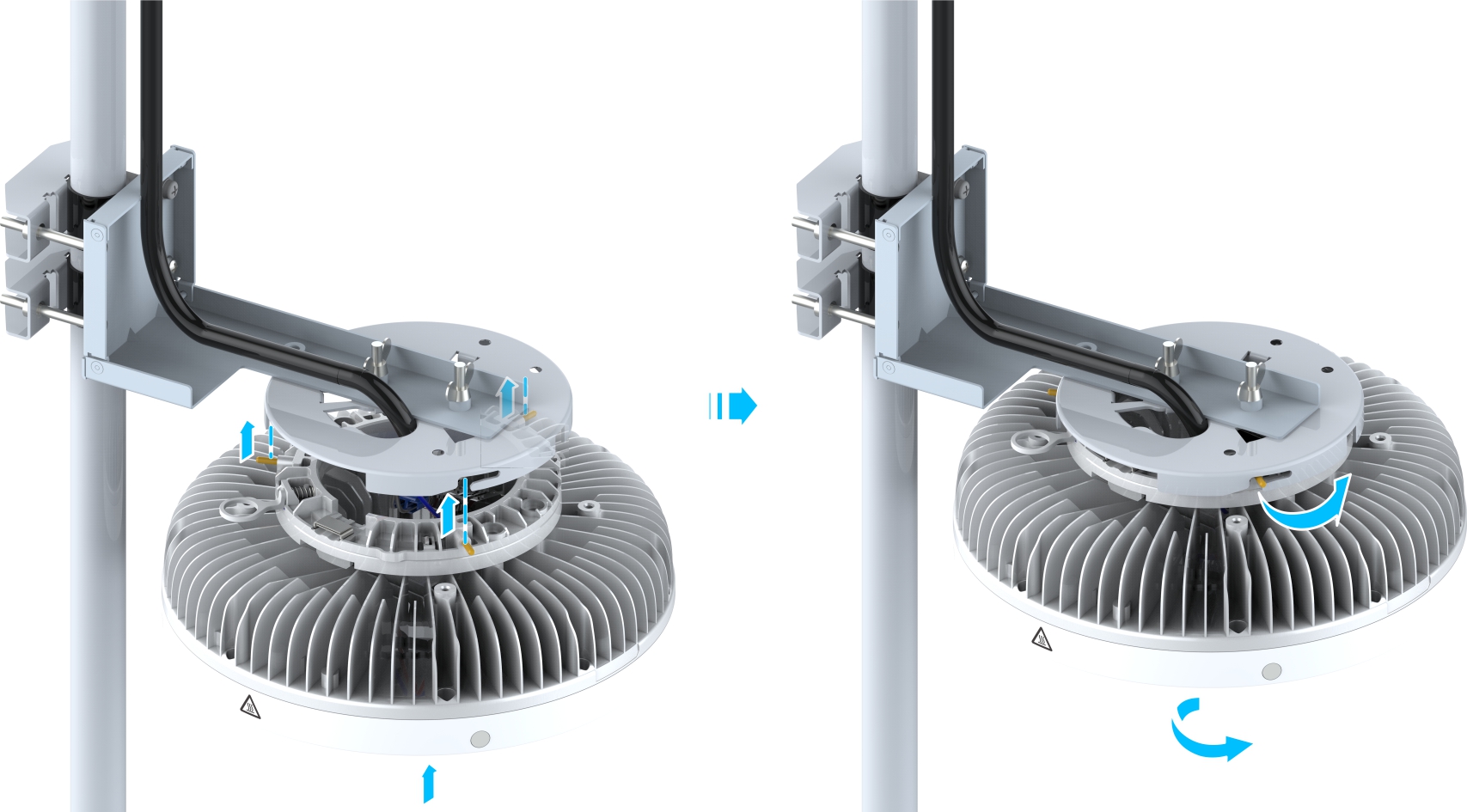
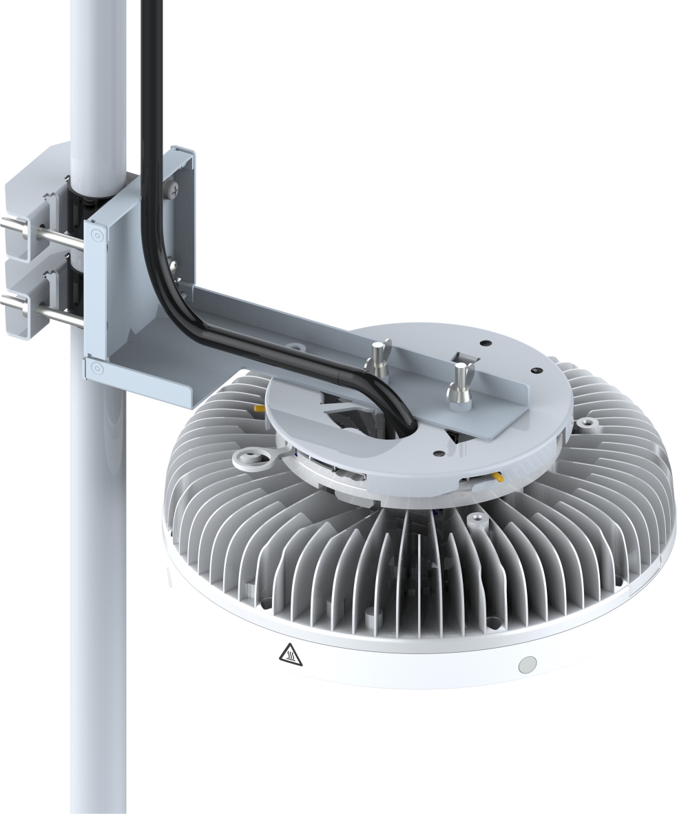
The following figure shows the device mounted on the pole.